The IIS Chip Gallery
MadMax (2012)

Additional pictures below, click to see larger versions


by


| Application | Graphics |
| Technology | 65 |
| Manufacturer | UMC |
| Type | Master Thesis |
| Package | CQFP120 |
| Dimensions | 3772μm x 3772μm |
| Gates | 7 MGE |
| Voltage | 1.2 V |
| Power | 1.5 W |
| Clock | 400 MHz |
The quality of stereoscopic 3D (S3D) video is currently limited by display technology: projecting a stereo image pair on left and right eyes respectively does not provide an immersive 3D viewing experience. In particular, disturbing effects of current S3D are the necessity to wear glasses and missing motion parallax. Next generation 3D therefore relies on autostereoscopic displays, i.e., displays that provide an S3D effect without cumbersome glasses or the like. To lessen the problem of strong spatial confinement of autostereoscopic displays (the viewer is required to be at a very specific position in front of the display), modern autosteroscopic displays use multiple views of the same scene. Such displays are called multiview autostereoscopic displays (MADs).
The moving picture experts group (MPEG) issued a call for proposals for a multiview/3D coding and transmission standard. That is, the necessity of having multiple views of the same scene severly increases transmission and storage requirements. An approach for efficient multiview coding is crucial for reducing the highly redundant amount of data. In this work we consider the warping-based approach to multiview generation, coding, transmission, and decoding. It consists on transmitting two views (stereo pair) plus warp information to generate the intermediate views in the receiver.
In conjunction with the MPEG proposal described above, we design the first VLSI implementation of a view synthesis core for state-of-the-art MADs. The core takes a 2-view stereo sequence plus warping grids as input and produces high-quality, alias-free, multiview output streams at full HD resolution. The VLSI implementation serves as reference implementation for the MPEG standard candidate.
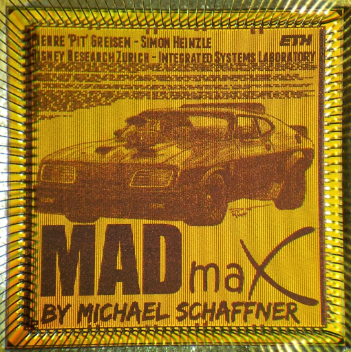
This work was realized as Master thesis at the Integrated Systems Laboratoray in conjuncture with Disney Research Zurich by Michael Schaffner under main supervision of Pierre Greisen. This text appears also on the chip
The chip shares its name with the movie Mad Max by George Miller from 1979. The artwork is the Interceptor used in the movie. The car has an interesting history that you can read about here. The artwork is by Dan Poll used and adapted with his permission.
The UMC65 nm technology has more than 50 different metallization options that you can choose from. For thisproject we have used the metal stack that is also used for the mini@sic programme offered through Europractice. It has 8 metal layers, out of which the highest one (metal 8) is very thick for applications that need to design inductors (which this design does not really need) with low parasitic resistance. As a result the top level metal is very thick, and is not very suitable for signal routing.

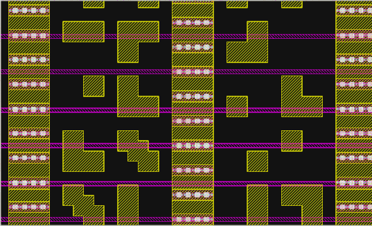
We have used the top metal layer as part of the power grid. So apart from the power connections, shown as yellow vertical stripes, there is nothing on that metal layer within the core area. We have written a small program that maps a two color picture on to the area in between the power stipes. The various rectangular shapes seen in yellow correspond to a 8x8 pixel part of the image. The Interceptor is 860 pixels wide and 380 pixels high. The pixels are sized to fullfill the minimum area requirements of the metal. The pink horizontal lines show the Metal 7, which forms the second part of the grid.
We had the time to add a slightly more elaborate logo on this chip because of several reasons. First of all the tape-out was delayed by one month due to lack of space on the MPW shuttle. So the design was completed a month in advance. Secondly this is a rather large design (16mm^2) and could live without routing signals on the top level, giving us the chance to place a large logo. Lastly, we have improved several of our logo generating scripts which made it easier to design larger artworks.