The IIS Chip Gallery
BPDS1 (2000)

by

| Application | Converter |
| Technology | 250 |
| Manufacturer | STM |
| Type | Research |
| Package | Baredie |
| Dimensions | 650μm x 550μm |
| Voltage | 2.5 V |
| Power | 13.5 mW |
The third generation mobile phones are poised to be deployed in many parts of the world in the next couple of years. Dictated by the overwhelming popularity of its second generation predecessors such as GSM, one of the requirements for a third generation mobile phone is that it be dual or multi-standard.
The circuit combines GSM and WCDMA, the most important third generation standard, as receiver section for intermediate frequency reception, frequency translation to DC and subsequent conversion to digital. Due to the spectral shaping of quantization noise the latter provides an efficient trade-off bandwidth and resolution which has been exploited to accommodate the 25-fold difference in channel bandwidth between GSM (200 kHz) and WCDMA (5 MHz). The design has been optimized for both applications. For WCDMA, an additional zero has been added at the upper band edge. The circuit implemented with switched-capacitor technique is capable of processing input signals at an IF as high as 100 MHz with more than 80 dB of dynamic range for GSM and more than 50 dB for WCDMA at a power consumption in the order of 10 mW which makes it very attractive for practical use.
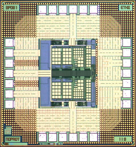
The chip photomicrograph shows I- and Qchannels laid out in a symmetrical way. They share the timing generation and the clock bus in the middle which is surrounded by the switches. The capacitor arrays consume most of the area, with larger capacitors for the input stage (upper side). OTAs, bias and comparators are placed at the outer side of the core area to minimize distortion from the digital parts. The core measures 650 um by 550 um. The joint project with Philips Semiconductors has been funded by KTI (Swiss Commission for Technology and Innovation).